461 Results
View results:
Sort by:

The data exchange between RFEM 6 and Allplan can be done using various file formats. This article describes the data exchange of a determined surface reinforcement using the ASF interface. This allows you to display the RFEM reinforcement values as level curves or colored reinforcement images in Allplan.
If you want to apply, for example, wind loads to a circular cylinder as defined in EN 1991‑4, Clause 7.9, proceed as follows.
RFEM and RSTAB provide a wide range of selection options. Some of the previous posts have already described selection using "Special Selection" or tables.
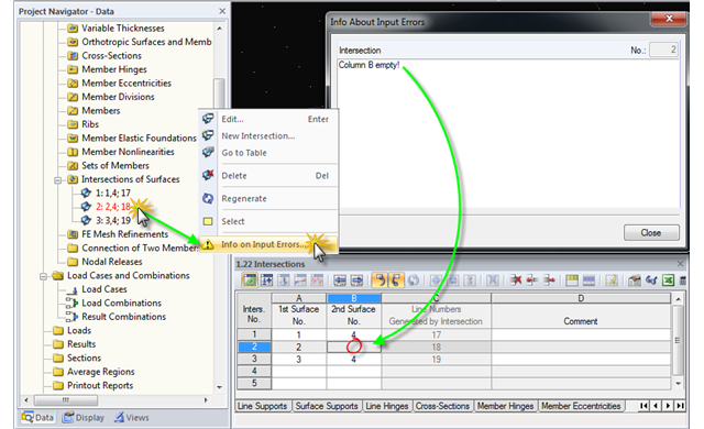
When modeling structural systems or loads, input errors or faulty objects may occur due to subsequent modifications, displacements, and adjustments in the model.
You can select an object in RFEM or RSTAB by simply clicking it. However, only the last object clicked will stay selected. In order to select several objects at a time, press the Control key while clicking. Since this procedure is not always possible, you can use the "Add to Selection" function in the toolbar or in the "Edit" → "Select" menu.
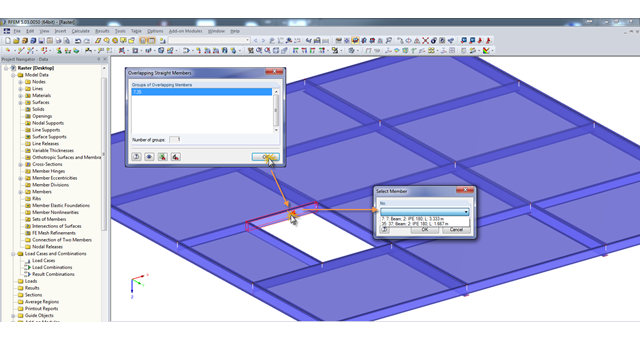
A modell check allows you to find overlapping members, among other things. However, this targeted selection could cause some minor problems. Therefore, there is a selection window now available, which appears when you click on one of the elements. This appears by clicking on one of the elements. Additional information helps you to select the correct member.
You may already be familiar with the "Center of Gravity and Info" function, which can be accessed using the shortcut menu of any element. If you want to display this information on several elements consecutively, you have to close the dialog box and open the shortcut menu of the next element over and over again.
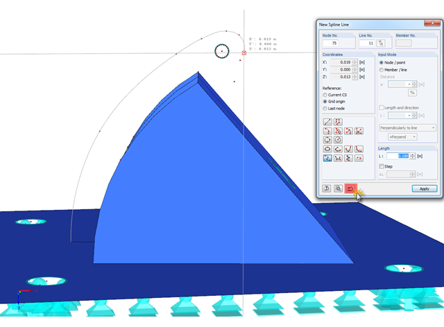
In RFEM, if you want to display a curved geometry (preferably in one continuous line), you can use splines or NURBS, for example. When modeling, you should pick the individual nodes one after another. If a mistake is made, you can go back using the special Undo function in the "New Spline Line" window. Thus, it is not necessary to enter the entire continuous line again.

With the "Info About Object..." function available in the menu under "Tools", you can display all the information about an object by placing the cursor on it in the graphical window.
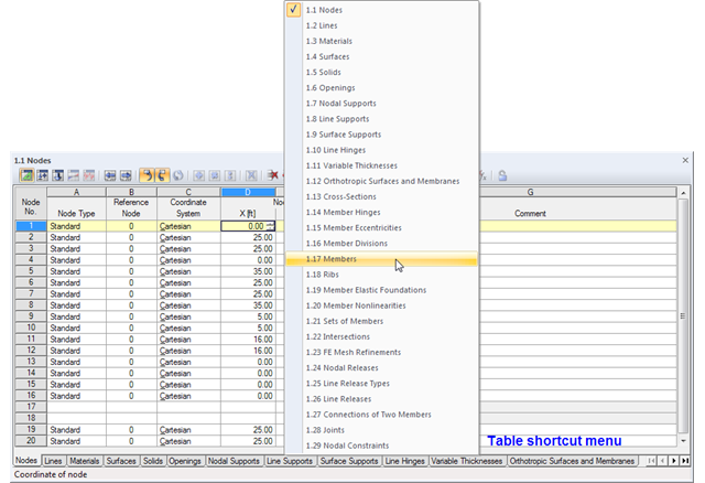
The geometry data of an RFEM model are currently managed in 29 tables, so not all of the tabs are displayed at once. To open a particular table, we recommend using the navigation menu that you can open by right-clicking on any tab. A shortcut menu appears, where you can quickly access the desired input table.
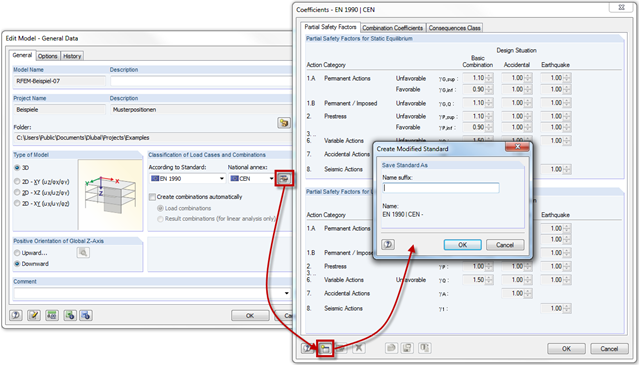
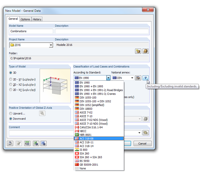
RFEM and RSTAB provide the option to create load and result combinations automatically according to the combination expressions defined in the standards. Partial safety factors and combination coefficients are specified in the standards or National Annexes. You can customize them as necessary and save them in a modified standard.
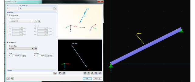
In RFEM and RSTAB, you can now rotate nodal loads or apply them on member axes. Thus, inclined members can also be loaded with nodal loads perpendicularly or along the member axis.
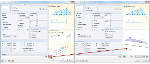
In addition to the load direction and reference length of member loads, it is now possible to display a preview of the loading.

Surfaces can be created using the "Surface via Line Extrusion" function by extruding lines perpendicular to the active work plane. The Video (WMV) shows how to use this function.
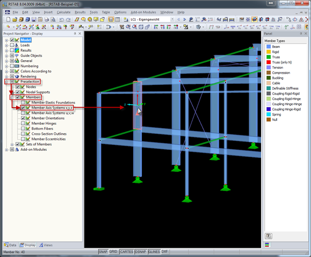
The local coordinate system of a member is particularly important when defining member end releases and member nonlinearities. The definitions follow the orientation of the axes. You can temporarily adjust the visibility of these member axes by means of preselection.
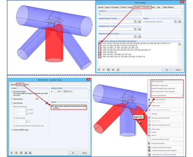
If intersections created in RFEM 4 are opened in an RFEM 5 file, the file management of intersections remains in the old format for compatibility reasons. Thus, the individual partial surfaces of the intersection can be activated or deactivated using only the "Integrated/Components" tab, all partial surfaces can only have the same thickness, and it is impossible to use the separate FE mesh refinement for the individual surface components.
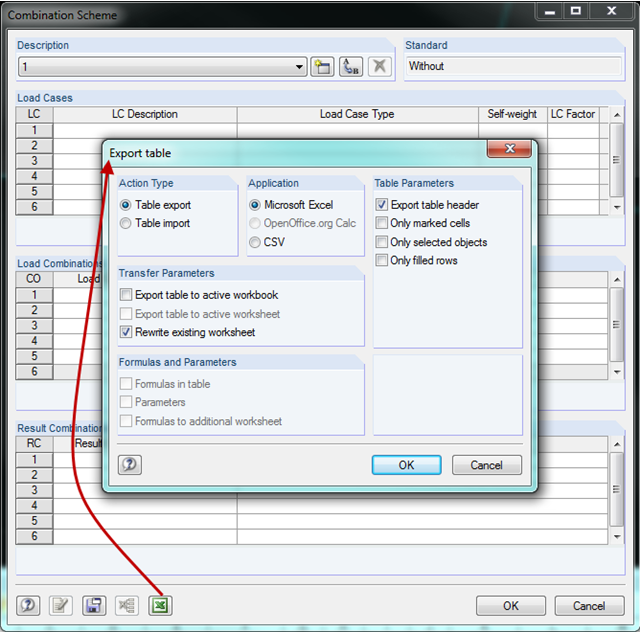
In RFEM and RSTAB, you can create a combination scheme in the combinatorics of load cases and combinations. This scheme can be used for other projects by transferring it to other computers using the Export/Import function. Thus, multiple people working on a project can use the same scheme.
In RFEM and RSTAB, load cases can be combined automatically using combination coefficients (partial safety factors) in order to determine the required design situations.
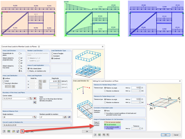
When generating member loads via plane, the program generates cells internally. These cells significantly influence the created member loads.
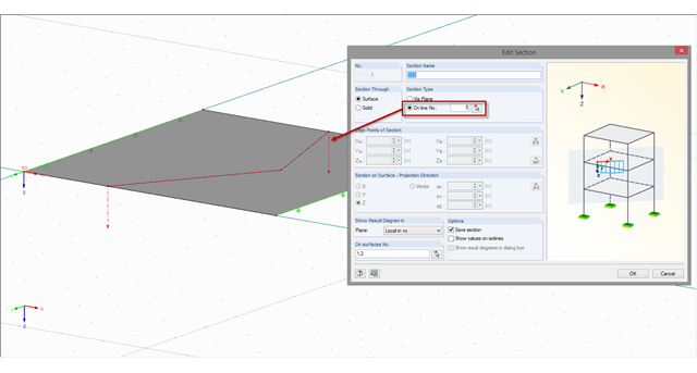
If a section is not on a straight line but on a curved or angled line, this line has to be defined accordingly as a polyline or a curved line. You can define the section along a line using the "Create Section Numerically" function.
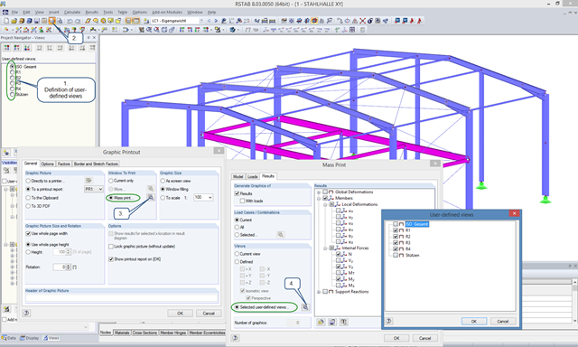
User-defined views are a very useful tool for effective modeling, as the previously selected and adapted objects appear directly with a click of the mouse. These objects can also be used easily to create informative and clearly arranged result graphics. With just a few clicks, you can create all result graphics at once using the mass print function.

When calculating foundations according to EC 7 or EC 2, different foundation types or sizes are usually used in one object. However, boundary conditions like the soil parameters, the materials for foundations, concrete covers, and the load combinations selected for design remain the same for all foundations, as a rule.
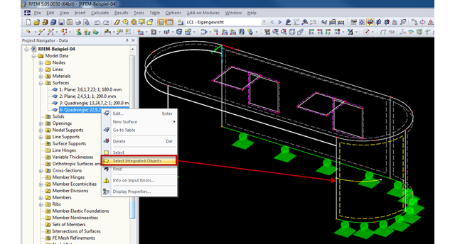
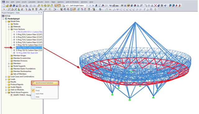
Generally, RFEM automatically detects all objects lying on a surface that are not used for surface definition. Objects integrated into surfaces can be selected using the "Select Integrated Objects" option in the shortcut menu of the relevant surface in Project Navigator. This way, you can easily find in the graphics which objects have already been integrated into a surface, for example.
You can use the selection functions to facilitate the input in the tables.
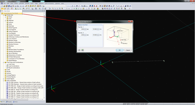
In RFEM and RSTAB, you can create nodes not only by means of coordinates, but also by means of existing nodes. You can use the "Node Between Two Points" function to create a node located on an imaginary line connecting two nodes. You can enter the distance as a percentage or according to the relative lengths.
RFEM and RSTAB provide numerous interfaces with other programs for data exchange. In the respective programs, different names are often used for the same materials and cross-sections. Therefore, it is necessary to convert the material and cross‑section names in order for them to be recognized by the program after the data exchange.
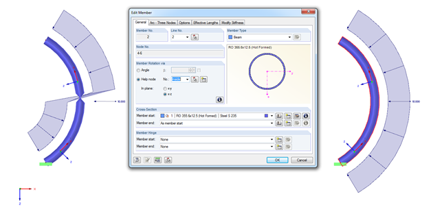
When modeling arc-shaped members, the problem shown in the figure may occur. It seems as if the member cross‑section is twisted or the load applied on the local z‑axis changes direction. How does this come about?
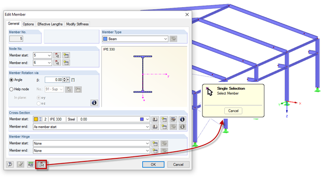
Member properties can be imported from the previously defined member in the "New Members" and "Edit Member" dialog boxes. To do this, click the [Select member and import its properties to the dialog box] button, then select the respective member.
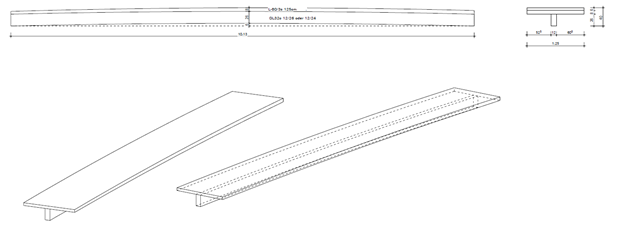
Our client had the exciting task of modeling a cross‑laminated timber plate with a precamber such that, in the case of a span of more than ten meters, the deformation was below the limit value of l/300 = 3.3 cm. The idea was to screw the plate on a glulam beam and then put it together with a glue approved by the building authorities in order to create a rigid bond between the plate and the member.
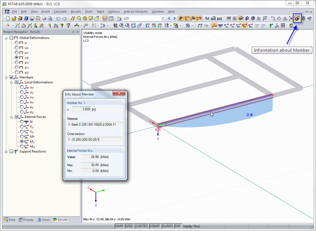
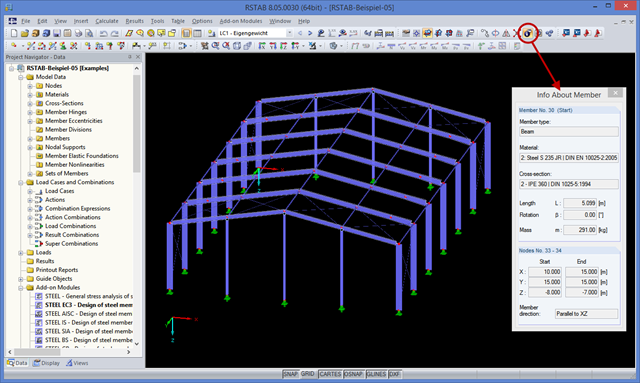
The "Info About Member" feature is available in RFEM and RSTAB. allows you to quickly read the member properties and results in a graphic. When you move the mouse over a member, the information about the member is displayed in the corresponding window.